
Bullet Camera Installation and Setup (XV-BULLET-1)
Camera Overview
XV Bullet Cameras with AlarmVision™ are indoor/outdoor video cameras that integrate with the XR Series™ Panel and feature on-edge analytics, including person and vehicle detection.
Virtual Keypad users can view live and recorded HD video clips, define video actions, and receive push notifications of real events in real time for real results.
You will need an active Dealer Admin account at dealer.securecomwireless.com to activate the camera.
Note: Ensure the XR Series Panel is updated to Version 241 or higher.
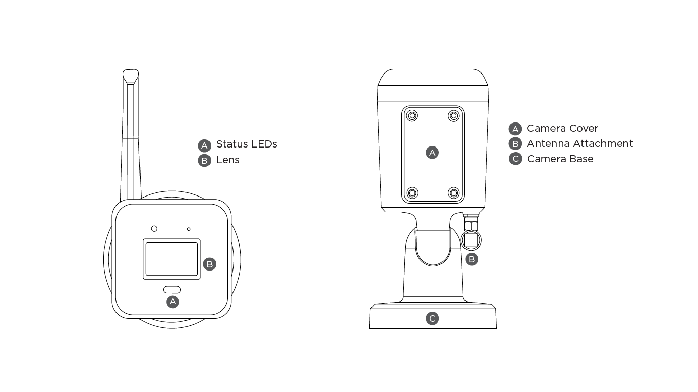
Bullet Camera Overview
What’s Included
XV Bullet Camera
Wi-Fi Antenna (Optional)
Weatherproofing Hardware Pack
Mounting Hardware Pack
Hex Key (Camera Base)
Torx Key (Camera Cover)
XV Camera Quick Start Guide
What You’ll Need
Phillips Screwdriver
3/16” Drill Bit
DMP Model V-12V-PS Plug In Power Supply (Optional, Non-POE or Wi-Fi Connection)
Wired Camera Installation
Pre-Installation (Bench Setup)
Prior to mounting the camera, activate the camera in Dealer Admin.
The camera does not need to be removed from the box for bench setup. Open the box to expose the cable connection ends and begin the onboarding process. To avoid overheating during bench setup, do not leave the camera powered on for more than 2 hours continuously while inside packaging.
Note: Bench setup should only be used for PoE or wired camera applications.
Power the Camera
Outdoor Installation
Slide the End Cap onto the Ethernet cable.
Attach the Plastic Seal to the Ethernet cable.
Slide the Cover onto the Ethernet cable and over the Plastic Seal.
Place the O-Ring around the camera Ethernet connector.
Connect the Ethernet cable to the camera Ethernet connector (Cat 5E or above).
Screw the Cover to the camera Ethernet connector with the O-Ring in between to lock into place.
Screw the End Cap and Cover together until tight.
Wrap tape around the Ethernet cable to secure the weatherproofing.
Connect the Ethernet cable to a Power over Ethernet (PoE) switch or injector.
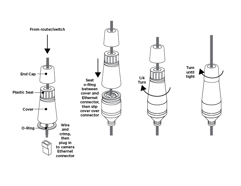
Installing the Waterproof Ethernet Cap
Indoor Installation
Connect a network cable from the camera’s Ethernet connector (Cat 5E or above) to a Power over Ethernet (PoE) switch or injector.
Wi-Fi Camera Installation
Power the Camera
Connect a DMP Model V-12V-PS Plug In Power Supply (not included) to the camera power connector.* Connect a network cable to the camera Ethernet connector.
Note: To use this camera with a Wi-Fi connection, remove the cap from the antenna connector. Then, attach the included antenna.
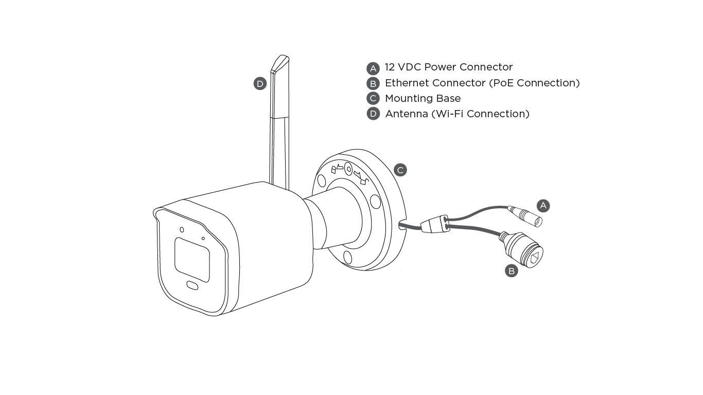
Bullet Camera Power Details
*Camera power connectors are compatible with 1 Amp or higher.
Mount the Camera
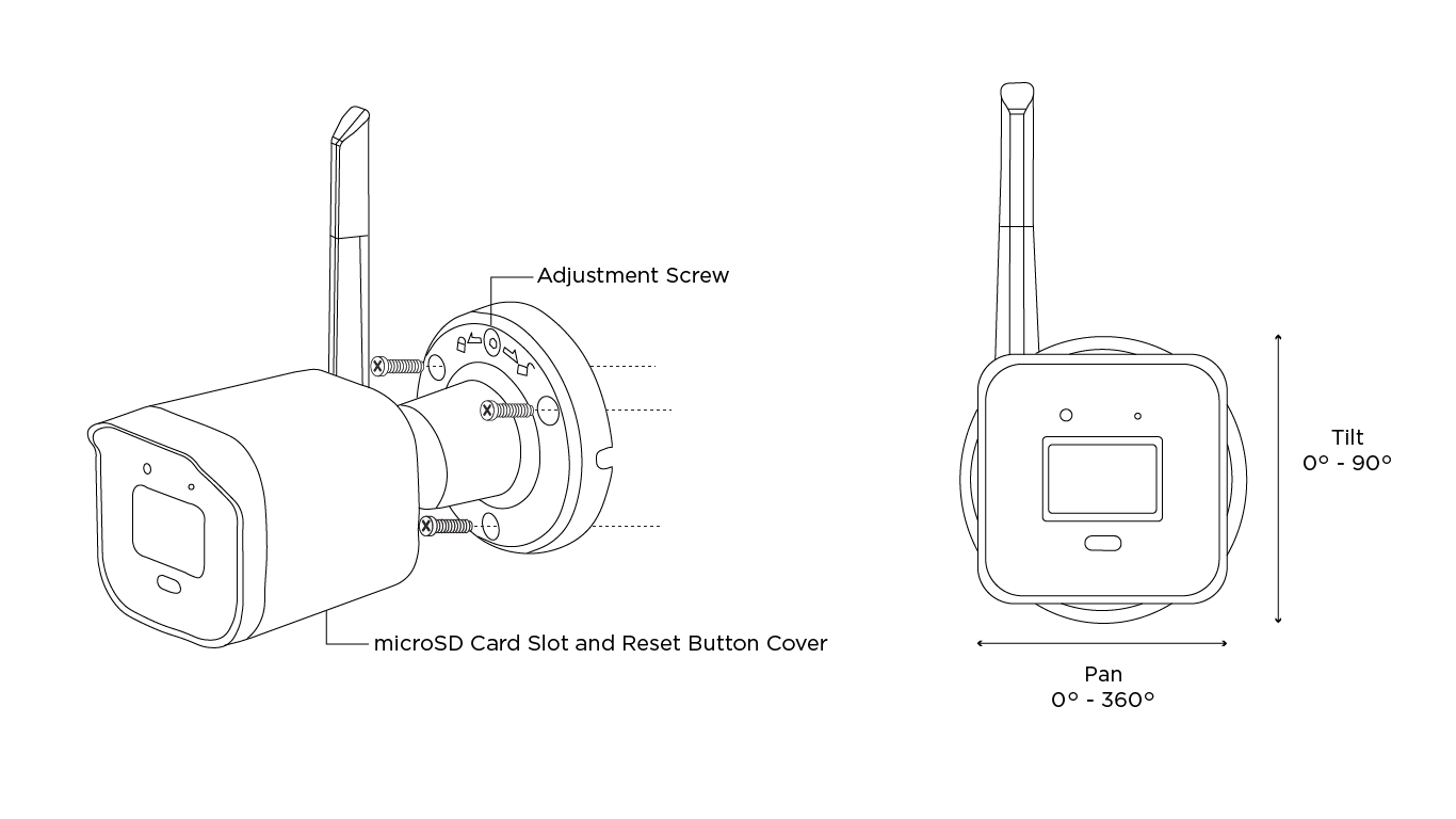
Mount and Adjust the Camera
Stick or place the mounting template at the location you want to mount the camera. Ensure the mounting template is properly placed for cable management.
Drill holes into the mounting template and insert the wall anchors in the holes (optional).
Loosen the adjustment screw at the camera base with the included hex key to change the camera angle.
Line up the camera base with the pre-drilled holes or wall anchors and use the included screws to mount the camera base.
Adjust the pan, tilt, and camera rotation angle as needed.
Tighten the adjustment screw at the camera base with the included hex key to lock the camera in place.
Note: The mounting surface should be capable of holding five times the camera’s weight.
Bullet Camera Mounting
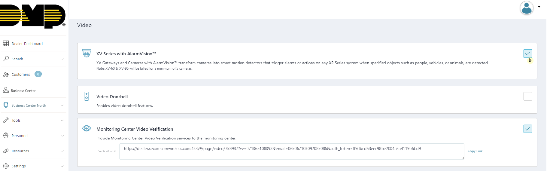
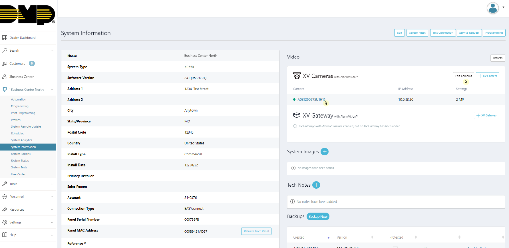
Enable XV Series Cameras with AlarmVision™
Log into Dealer Admin.
Find the customer and select the relevant system. Click Edit.
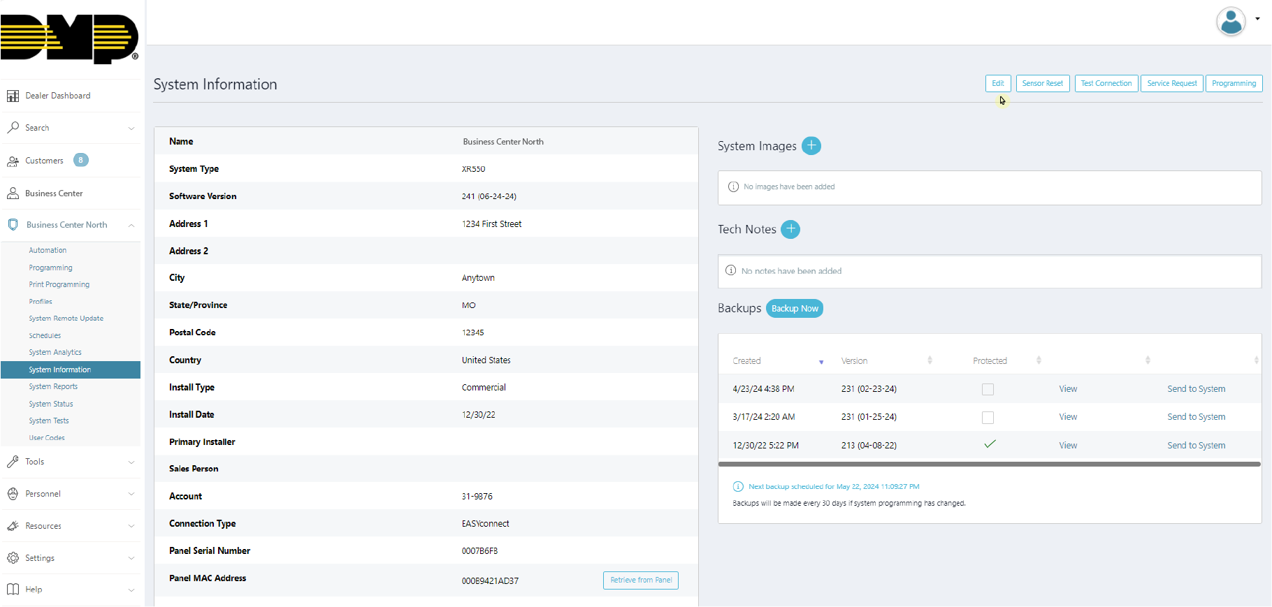
Edit a Customer’s System
In Video, click the XV Series with AlarmVision™ checkbox, then click Save.
Enable XV Series with AlarmVision™
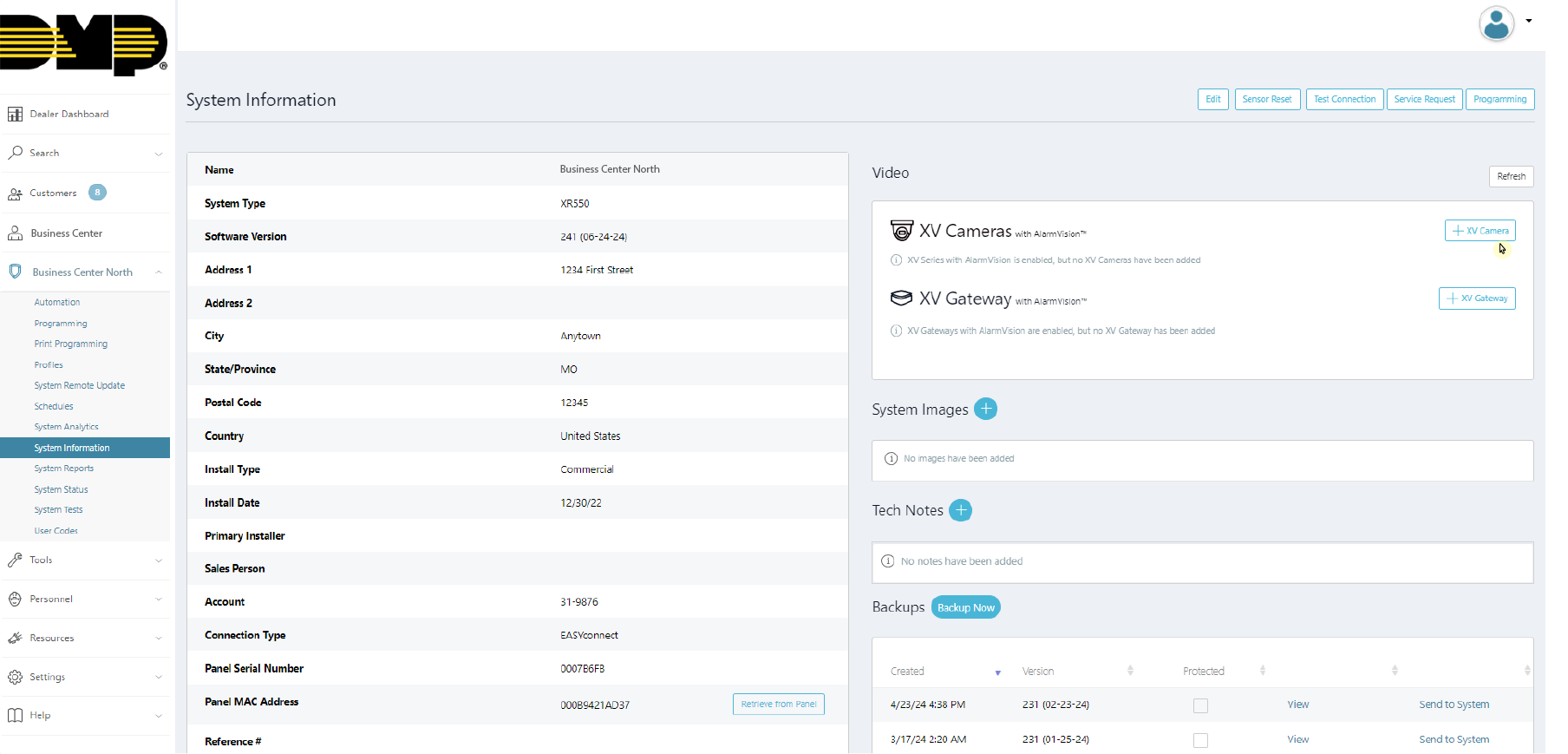
Add the Camera to System
XV Series bullet cameras can be added to the system in Dealer Admin via a PoE (Wired) connection or a Wi-Fi connection. To use a PoE (Wired) connection, refer to Option One. To use a Wi-Fi connection, refer to Option Two.
Option One: PoE (Wired) Connection
In the XV Series with AlarmVision™ section, click + XV Camera to add an XV Series camera.
Add an XV Series Camera
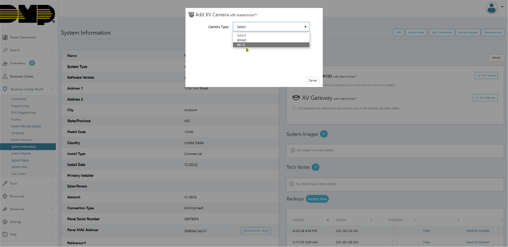
Select the Wired camera type.
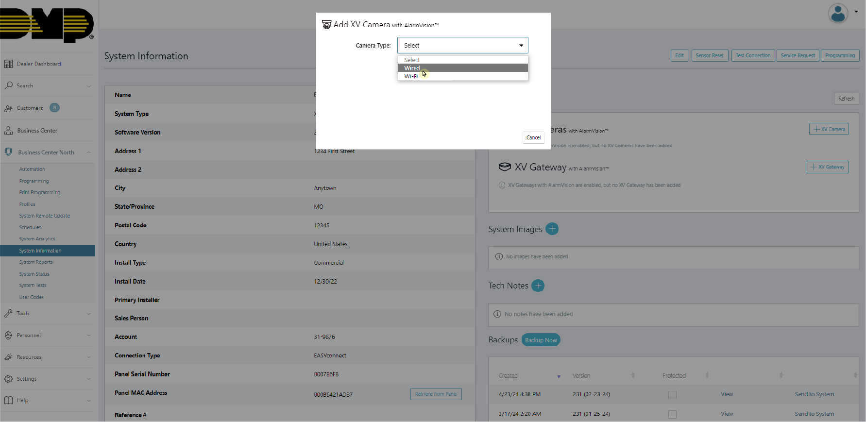
Select the Wired Camera Type
Add the camera Serial Number and click + XV Camera. You can find the camera serial number on the camera base or on the box the camera was shipped in.
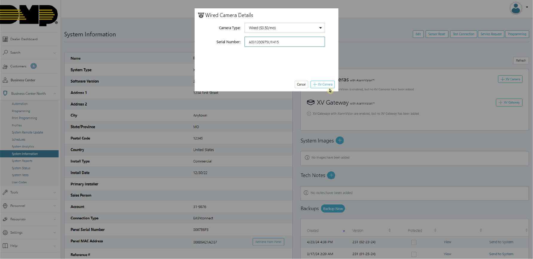
Add Wired Camera Details
To add the camera as a Camera Device Type, click Enable AlarmVision.
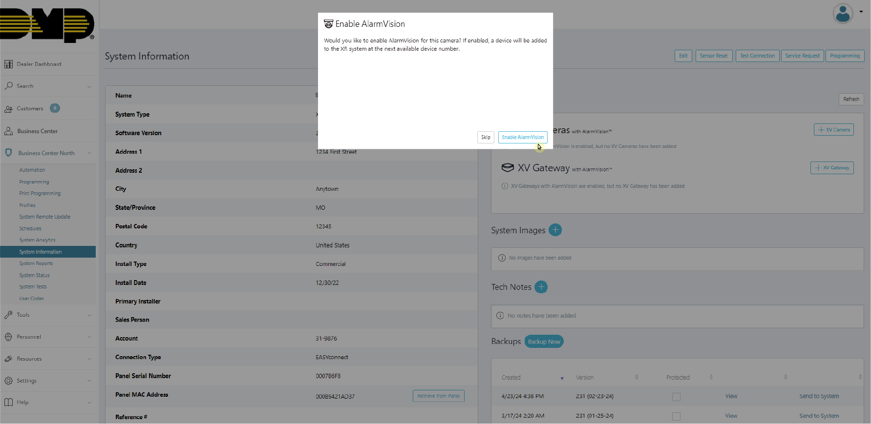
Enable AlarmVision for the Camera
Dealer Admin will display a green checkmark to the left of the camera serial number once it has been successfully added. Repeat this process to add additional cameras or click Save.
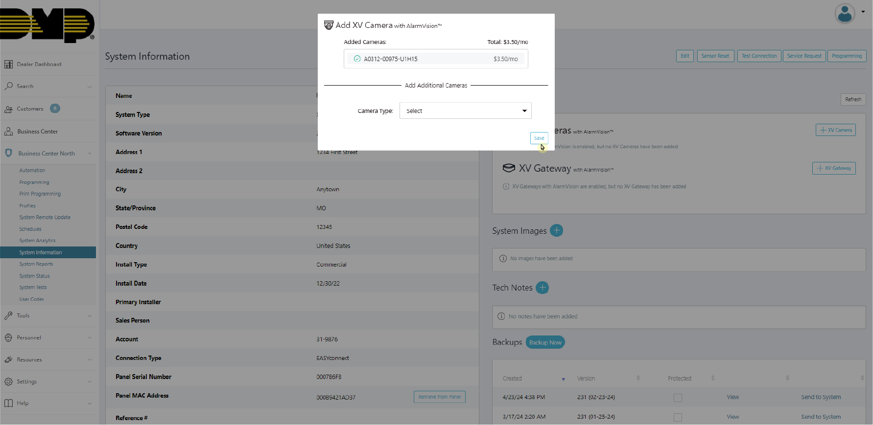
Add Additional Cameras and Save
Option Two: Wi-Fi Connection
In the XV Series with AlarmVision™ section, click + XV Camera to add an XV Series camera.
Add an XV Series Camera
Select the Wi-Fi camera type.
Select the Wi-Fi Camera Type
Type the Wi-Fi SSID and Wi-Fi Password that you want the camera connected to. Type in the camera Serial Number and click Generate QR Code.
Note: QR codes are single use per camera. Dealer Admin will provide the option to add additional Wi-Fi cameras after each camera has been added to the network.

Add Wi-Fi Camera Details
Hold the QR code in front of the camera lens until the blue LED begins to flash faster. Dealer Admin will automatically update after the camera has been successfully added. To troubleshoot camera issues, refer to the Camera Status LED List for more information.
Tip: Ensure screen brightness is up and protective coverings have been removed from the camera lens. Hold camera approximately 6-12inches from QR code and slowly adjust spacing until QR code is read.
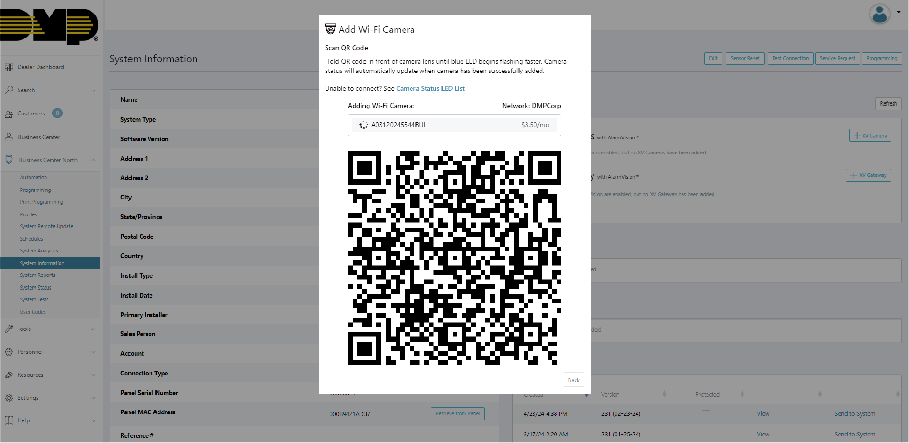
Generate a QR Code for Initial Camera
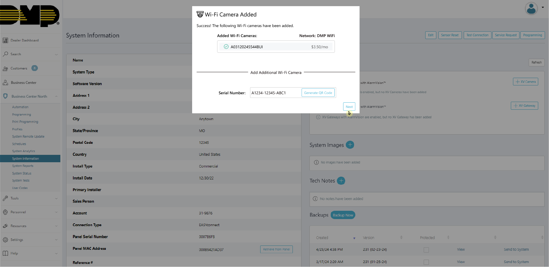
To add additional Wi-Fi cameras to the same network, enter the additional camera’s serial number and click Generate QR Code. Repeat step 4.
Generate QR Codes for Additional Cameras
To add the camera as a Camera Device Type, click Enable AlarmVision.
Enable AlarmVision for the Camera
When all of the Wi-Fi cameras have been added, click Next. Continue to add additional cameras to the system or click Save to finish activating the camera(s).
Add Additional Cameras and Save
To troubleshoot camera issues, refer to the Camera Status LED List for more information.
Edit the Camera
Select the camera(s) you want to edit.
Edit multiple cameras by clicking Edit Cameras in the XV Series with AlarmVision™ section.
Edit a single camera by clicking the camera name in the XV Series with AlarmVision™ section.
Select Camera(s) from XV Camera with AlarmVision™ Section
Enter a name for the camera.
Note: The camera name will default to the camera serial number.

Edit Camera Name
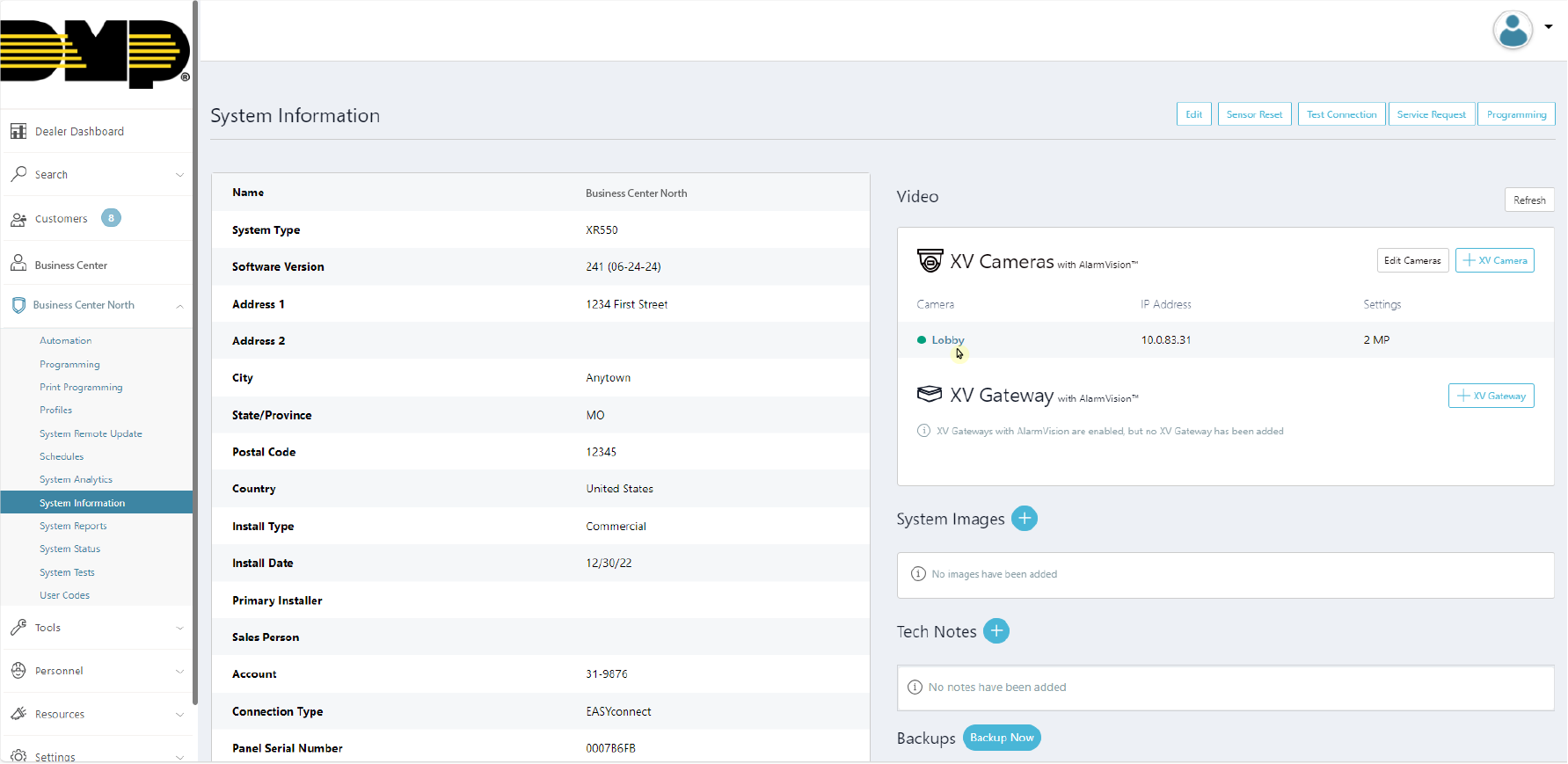
Click the Camera Details button in the top right corner to view the following camera information:
Camera Connection Status
Camera Name
MAC Address
IP Address
Resolution
Serial Number
Firmware Version
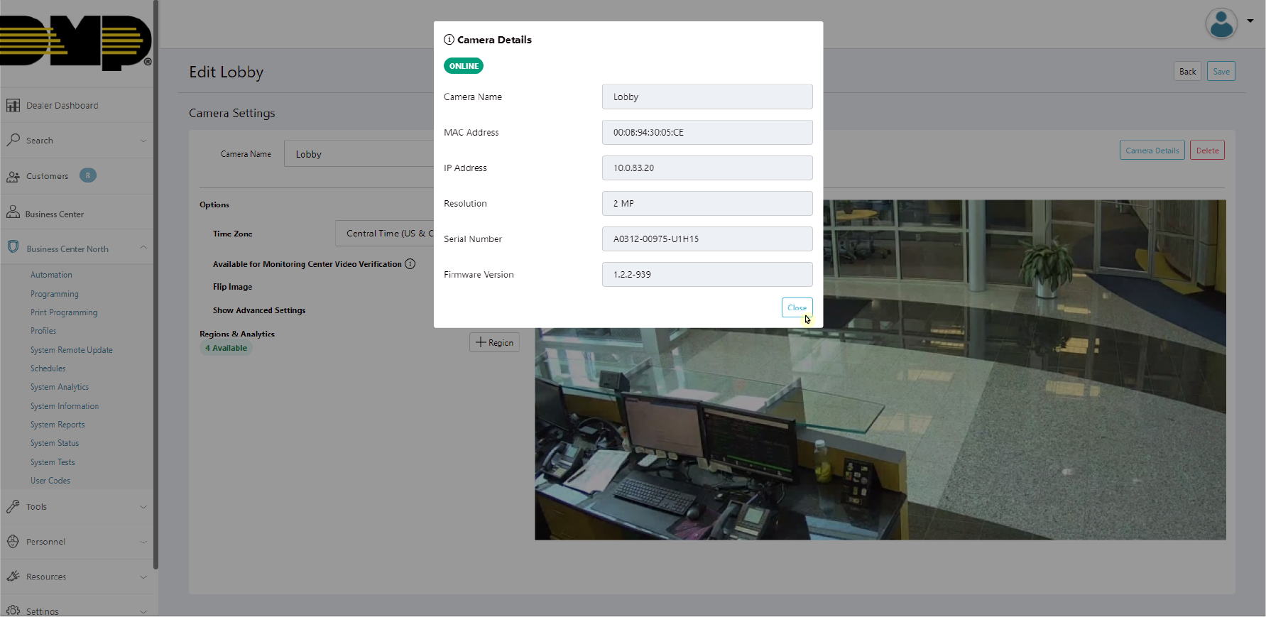
View Camera Details
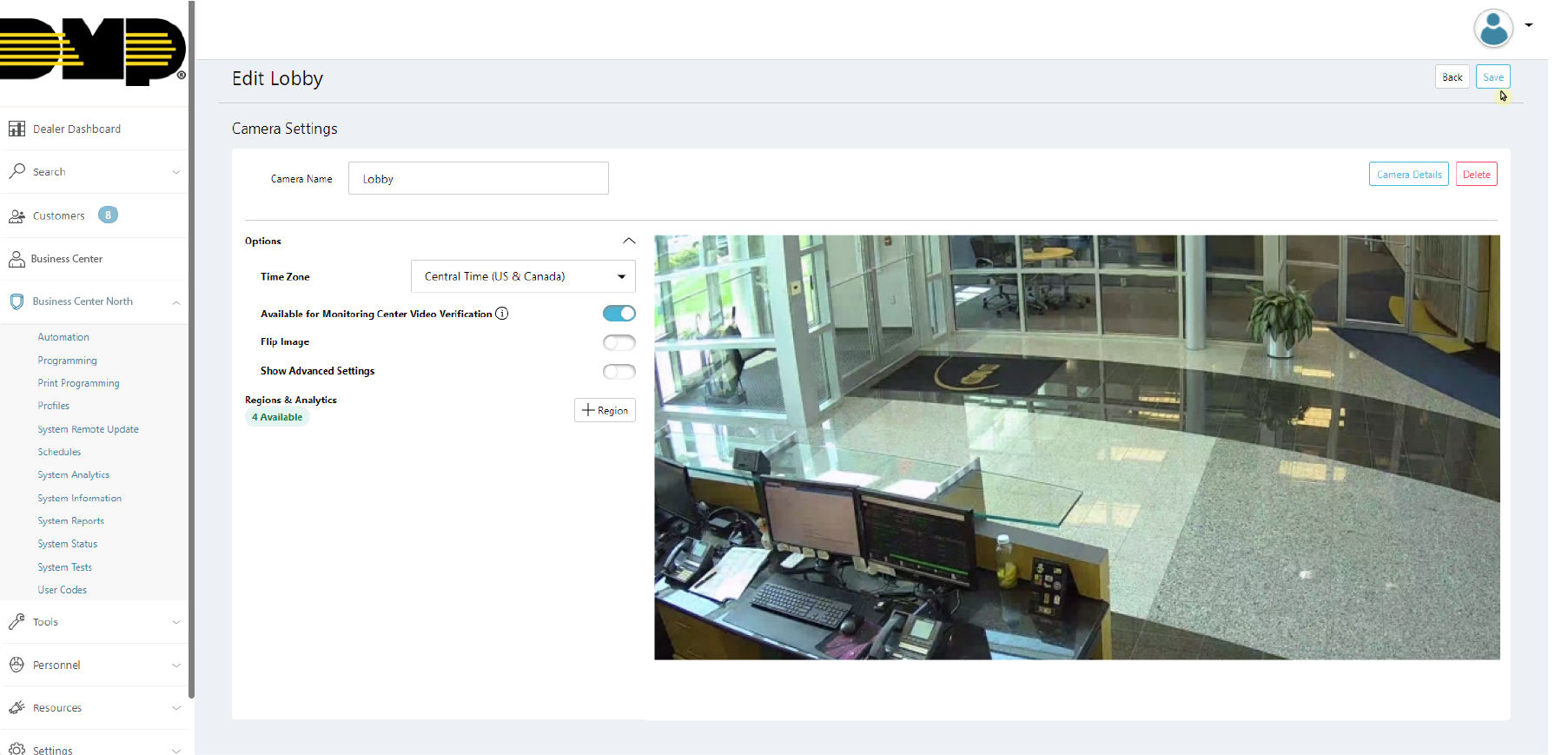
In Options, enable the following options:
Available for Monitoring Center Video Verification (if enabled for the system)
Flip Image (0, 180 degrees)
Show Advanced Settings
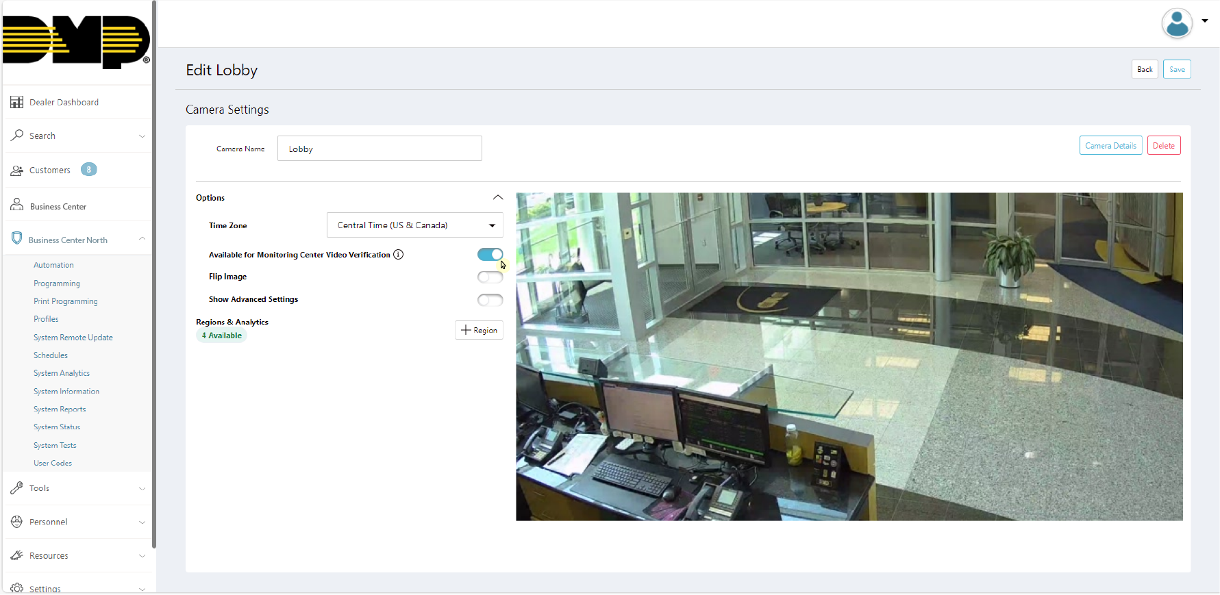
Enable Options Toggles
Click the Show Advanced Settings toggle to edit the following options:
Video Settings
Day/Night Mode
Video Quality
Image Settings
HDR (On/Off)
Brightness
Saturation
Contrast
Sharpness
Hue
Note: Click Reset to Default to restore Advanced Settings to DMP’s recommended settings.
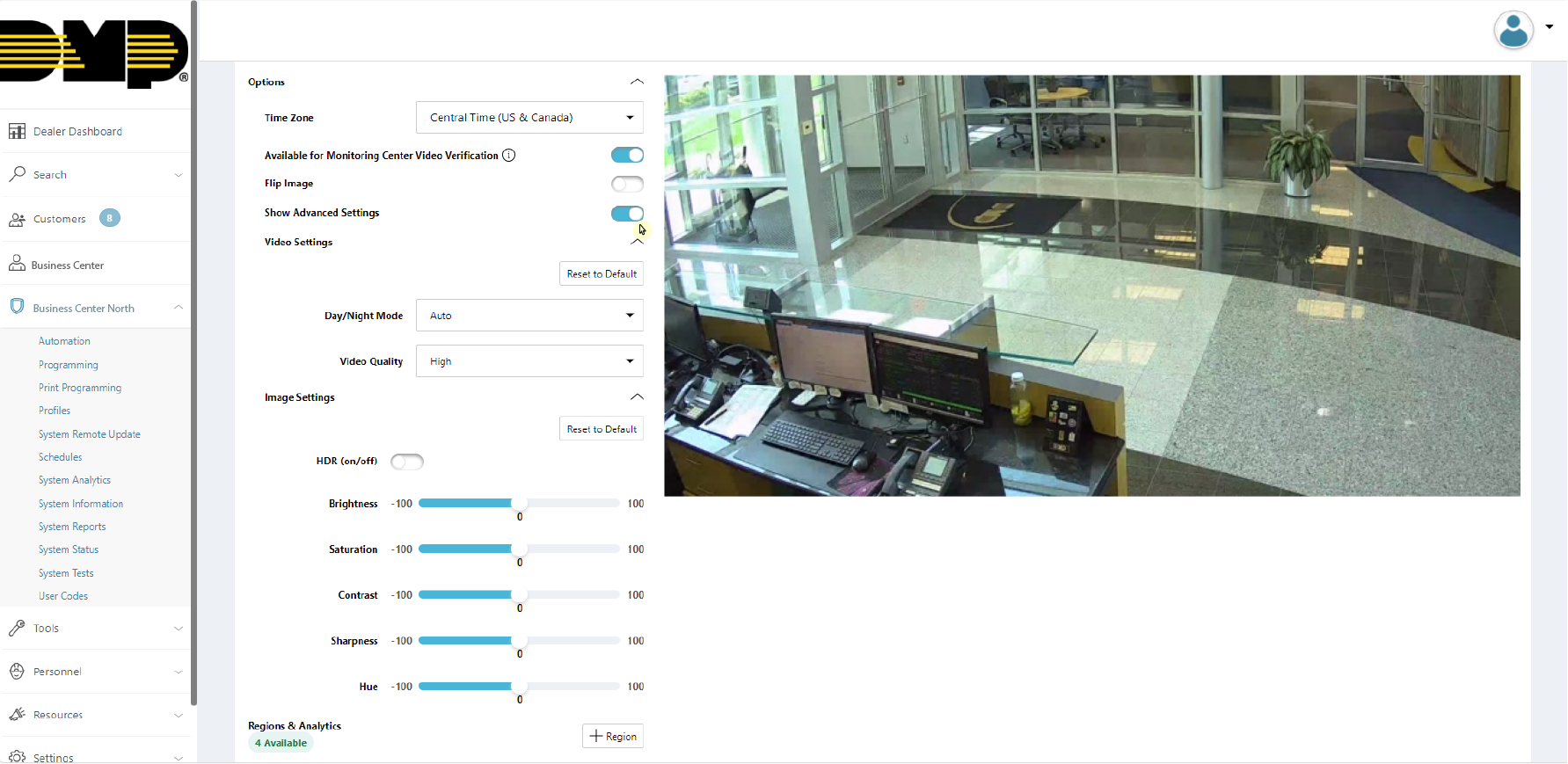
Enable Advanced Settings Toggle
Click Save in the top right corner to apply any edits to the camera.
Note: Clicking Save will exit the Edit Camera page. Refer to the Configure Detection Regions and Alarm Zones section below to configure the camera before exiting the page.
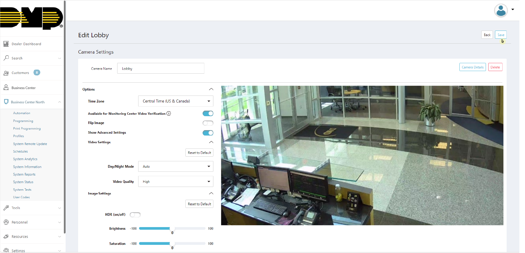
Save Camera Settings
Configure Detection Regions and Camera Alarm Zones
Create a Region
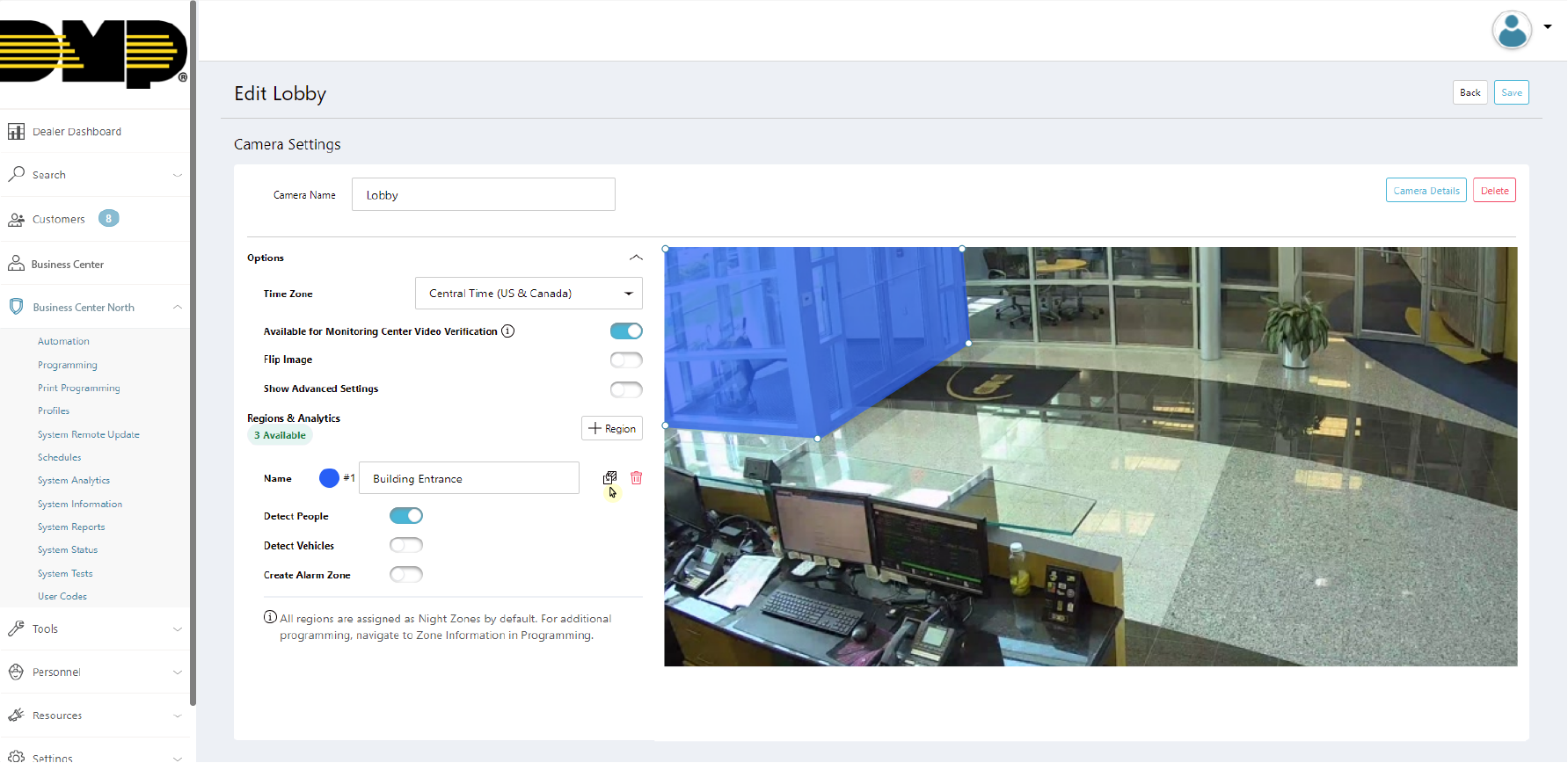
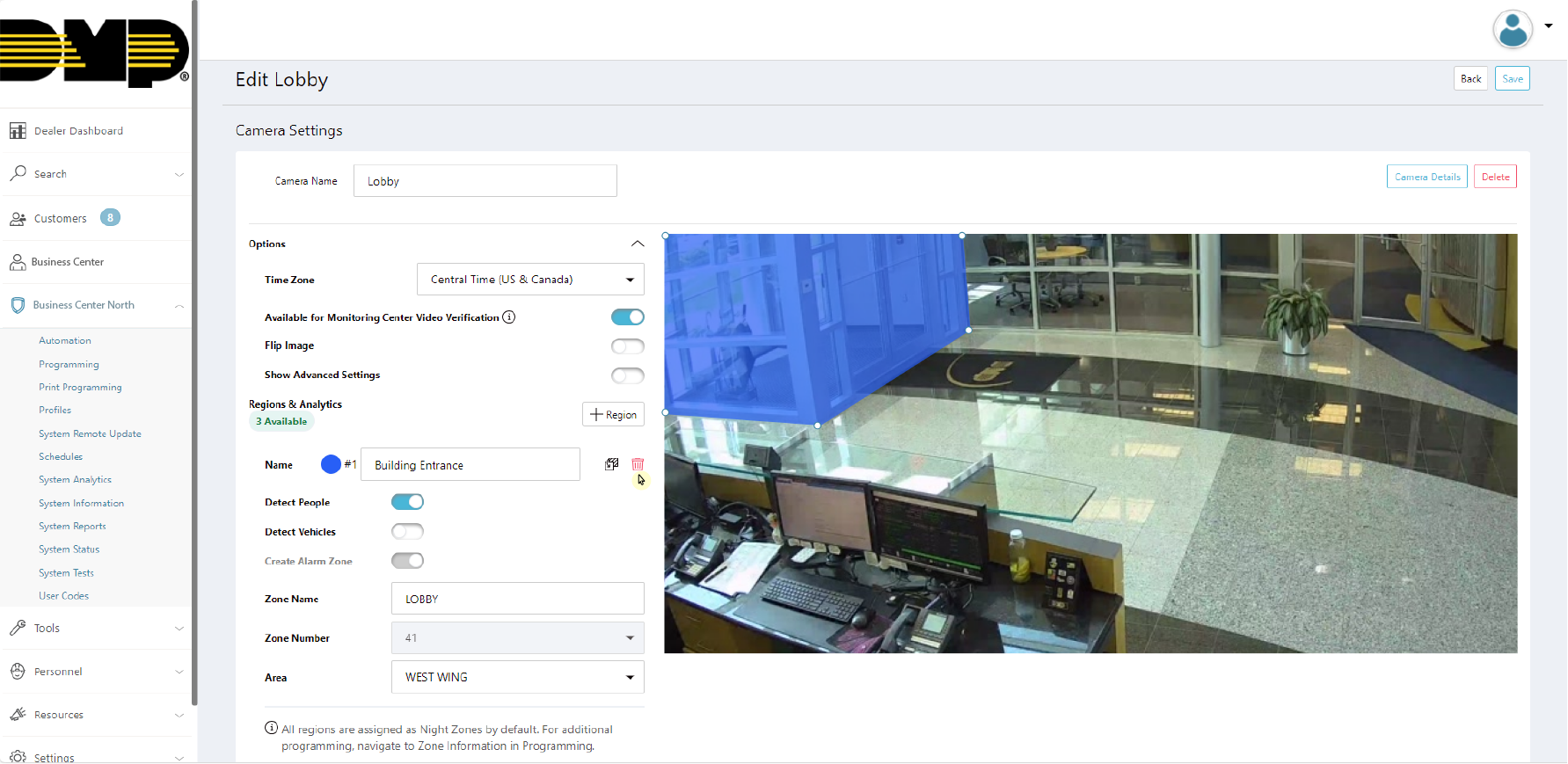
On the Edit Camera page, scroll down to Regions & Analytics and click + Region. A box will appear in the middle of the camera view screen. Click and drag the box on the camera’s field of view to define the desired detection region. Then, give the region a Name.
Note: Each camera can have up to four detection regions.
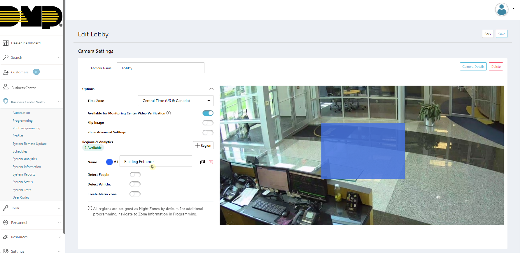
Add a Region and Give It a Name
Select whether you want the region to detect People, Vehicles, or both.

Select What the Region Will Detect
Click the boxes next to the name of the region. White circles will appear on the region box and can be used to manipulate the region by clicking and dragging them. You may also click anywhere on a line and a white circle will appear that allows the manipulation of the detection region.
Customize Detection Region Box
Add a Zone
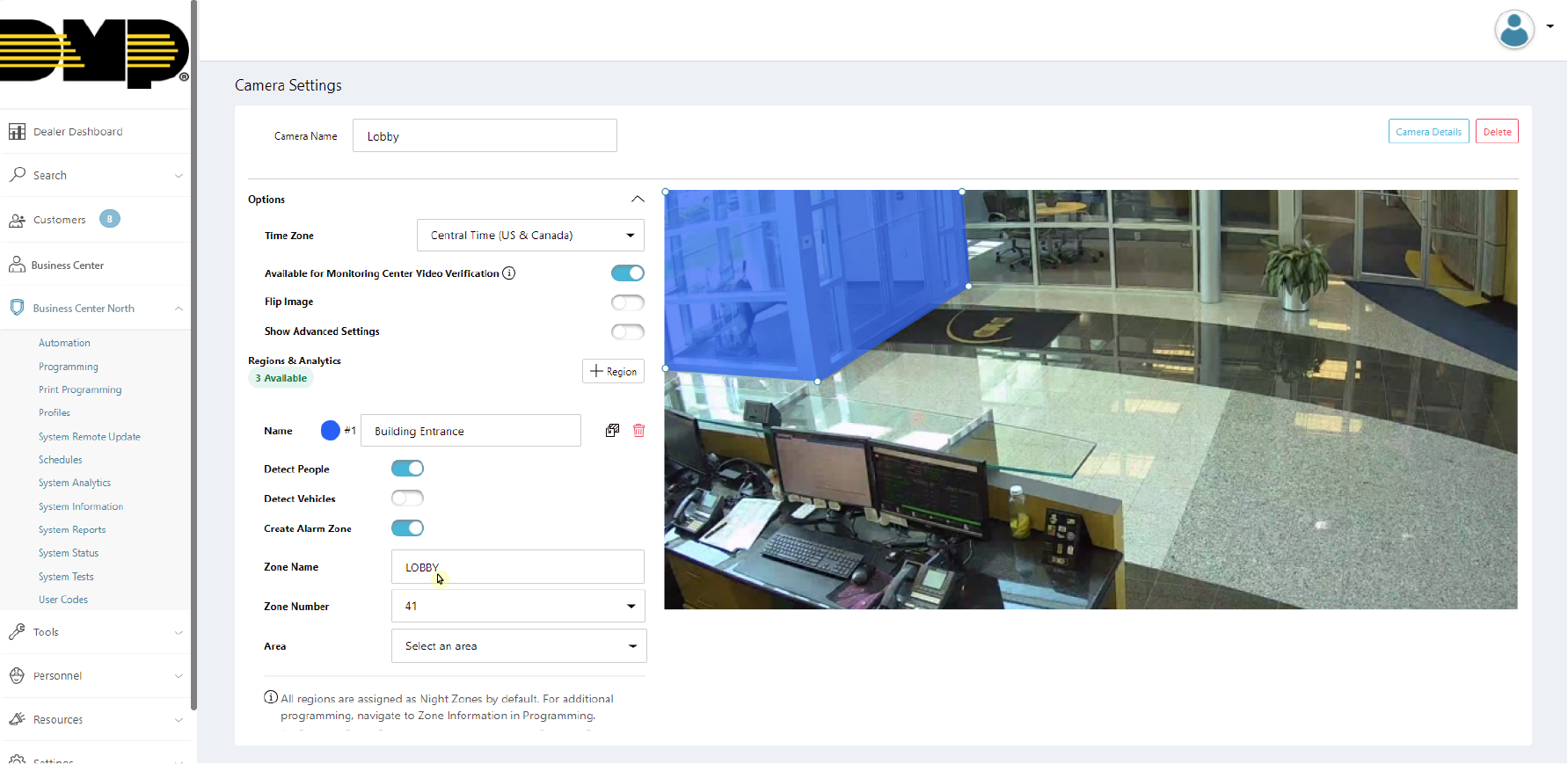
To tie a detection region to a panel zone, click the Create Alarm Zone toggle. This will expand into customizable zone options.
Note: If any camera detection region is tied to a panel zone, then all detections for that camera will only record when the zone is active.

Create an Alarm Zone
Give the zone a Name.
Assign a Name to an Alarm Zone
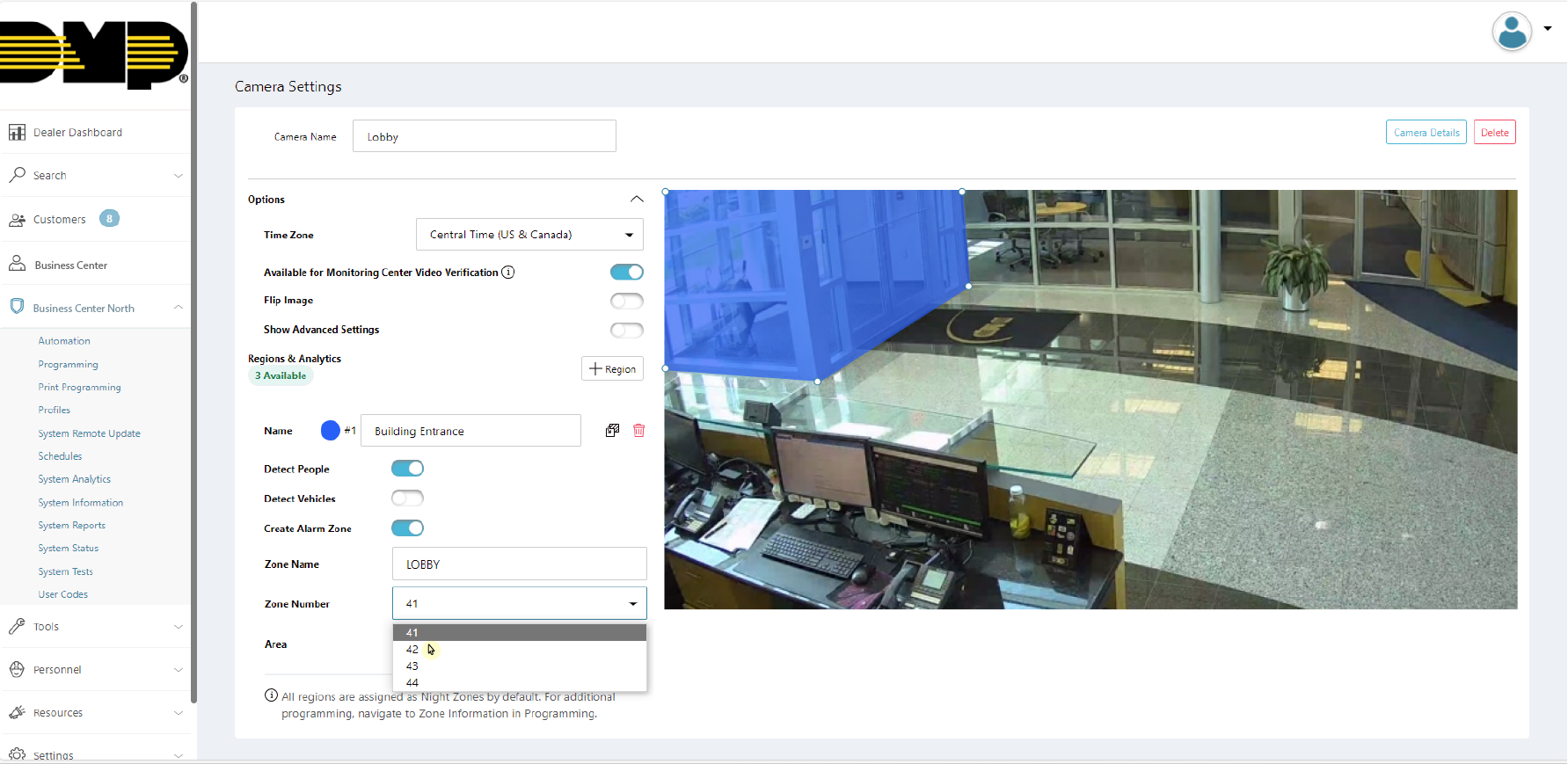
The zone number will automatically be populated with the next available zone number in the XR Series panel. You may assign a different zone number, if desired. Usable zones are LX500-999.
Note: Zones cannot be assigned to an AX-Bus.
Assign a Number to an Alarm Zone
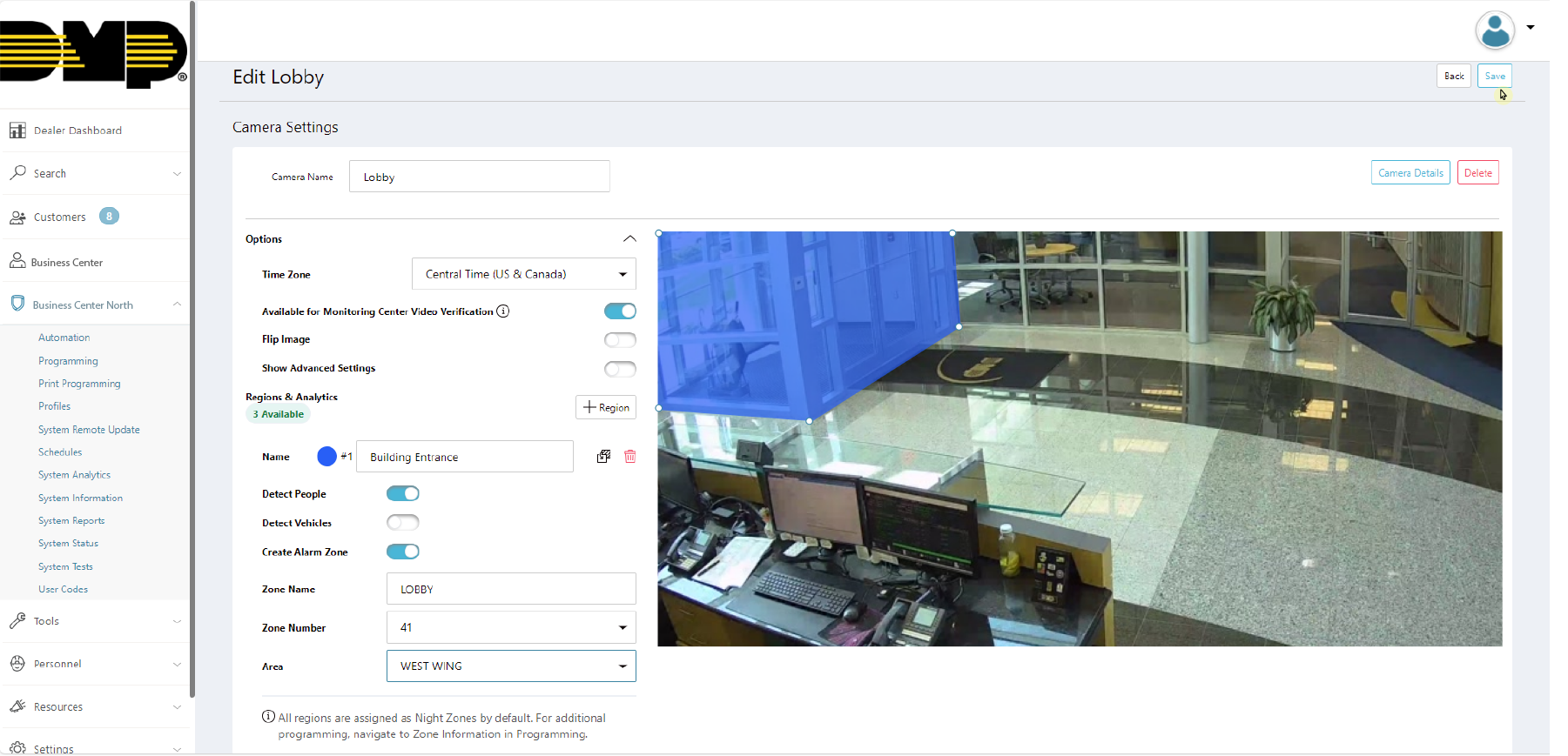
Assign the zone to an Area by selecting the drop-down menu.

Assign an Area to an Alarm Zone
To add additional detection regions, repeat steps 1-4. Up to four detection regions can be placed on a camera.
Note: All zones are programmed as a Night Zone by default. To edit zone programming, refer to the Edit a Zone section below.
Click Save to apply changes and exit the Edit Camera page. This saves the detection regions and any zones tied to them as well as any camera adjustments made previously.
Save a Detection Region and Alarm Zone
To configure end user settings, refer to Virtual Keypad Setup for more information.
Additional Camera Information
Edit a Device
To edit a device, navigate to Programming for the selected system.
Navigate to Device Setup and locate the camera device that needs to be edited.
Select the Device Name box and type in a new name for the camera device.
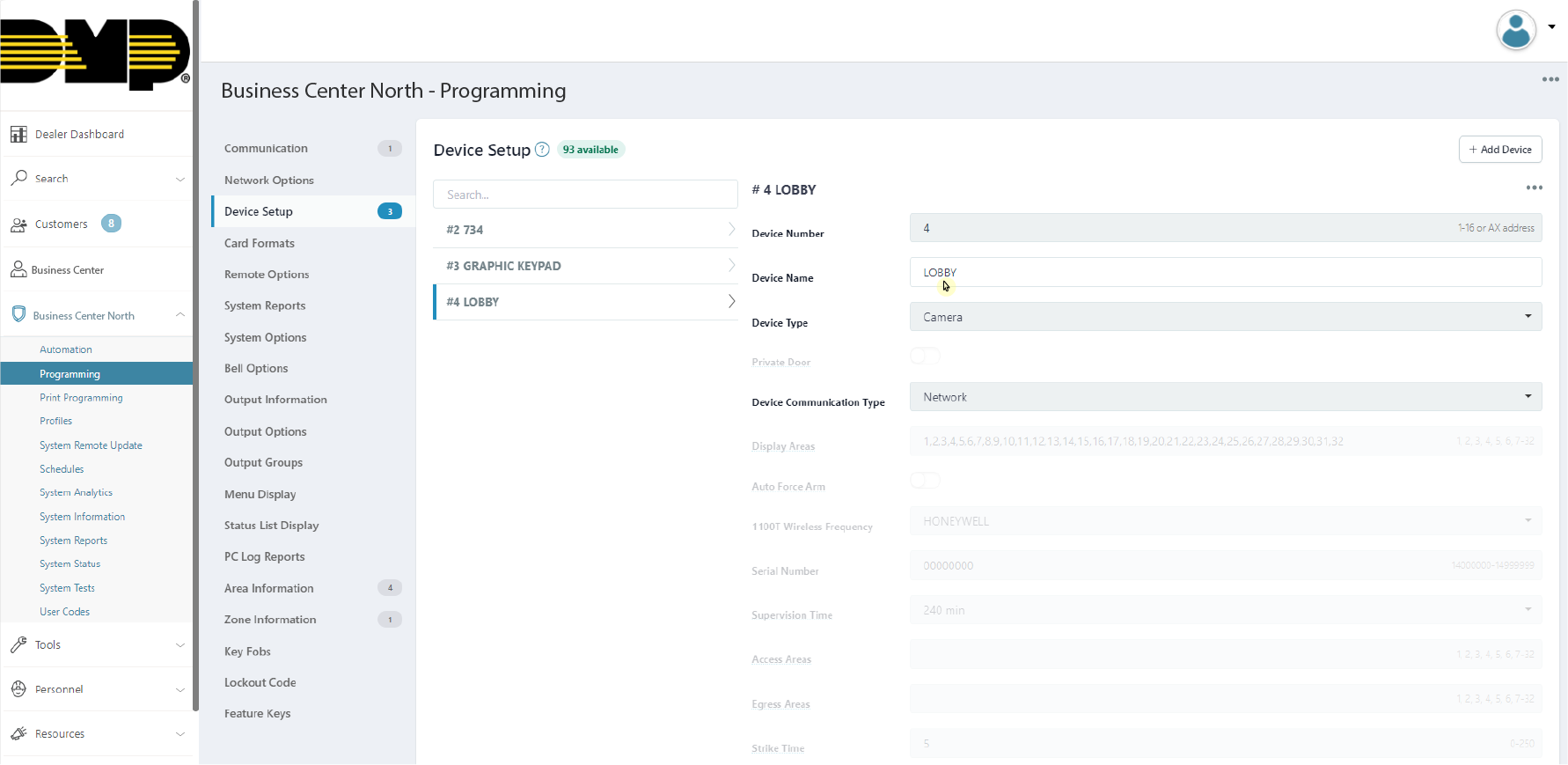
Edit Camera Device Type
When done editing, select Send All Changes in the top right corner of the screen to save the changes and send them to the panel.
Edit a Zone
To edit a zone, navigate to Programming for the selected system.
Navigate to Zone Information and locate the zone that needs to be edited.
Select the drop-down menu next to Zone Type. This displays the zone types that can be assigned.
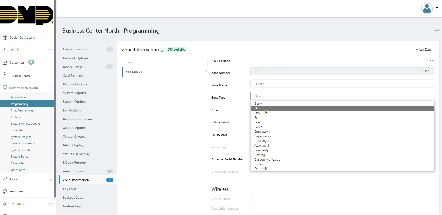
Select Zone Type
Select the drop-down menu next to Zone Actions. This displays the outputs that can be assigned.
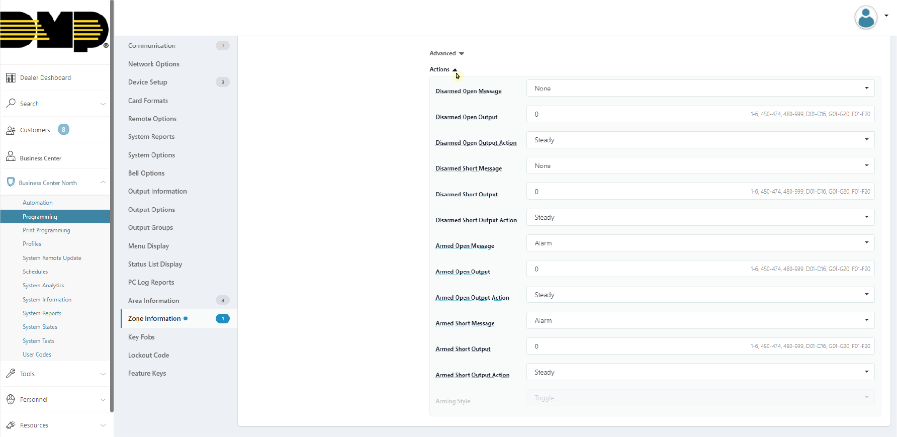
Select Zone Action
When done editing, select Send All Changes in the top right corner of the screen to save the changes and send them to the panel.
Delete a Detection Region and Zone
To delete a detection region and a zone tied to it, navigate to System Information for the selected system.
Note: Zones should NOT be deleted from Zone Information. If you attempt to delete a zone this way, a message appears explaining that the panel’s detection region will not properly communicate with the panel.
Select the camera that is tied to the detection region.

Select a Camera to Delete a Detection Region
Click the Trash Can icon next to the name of the detection region.
Delete a Detection Region
Click Save. This deletes the detection region and any zone tied to it.
Save Camera Settings After Deleting a Detection Region
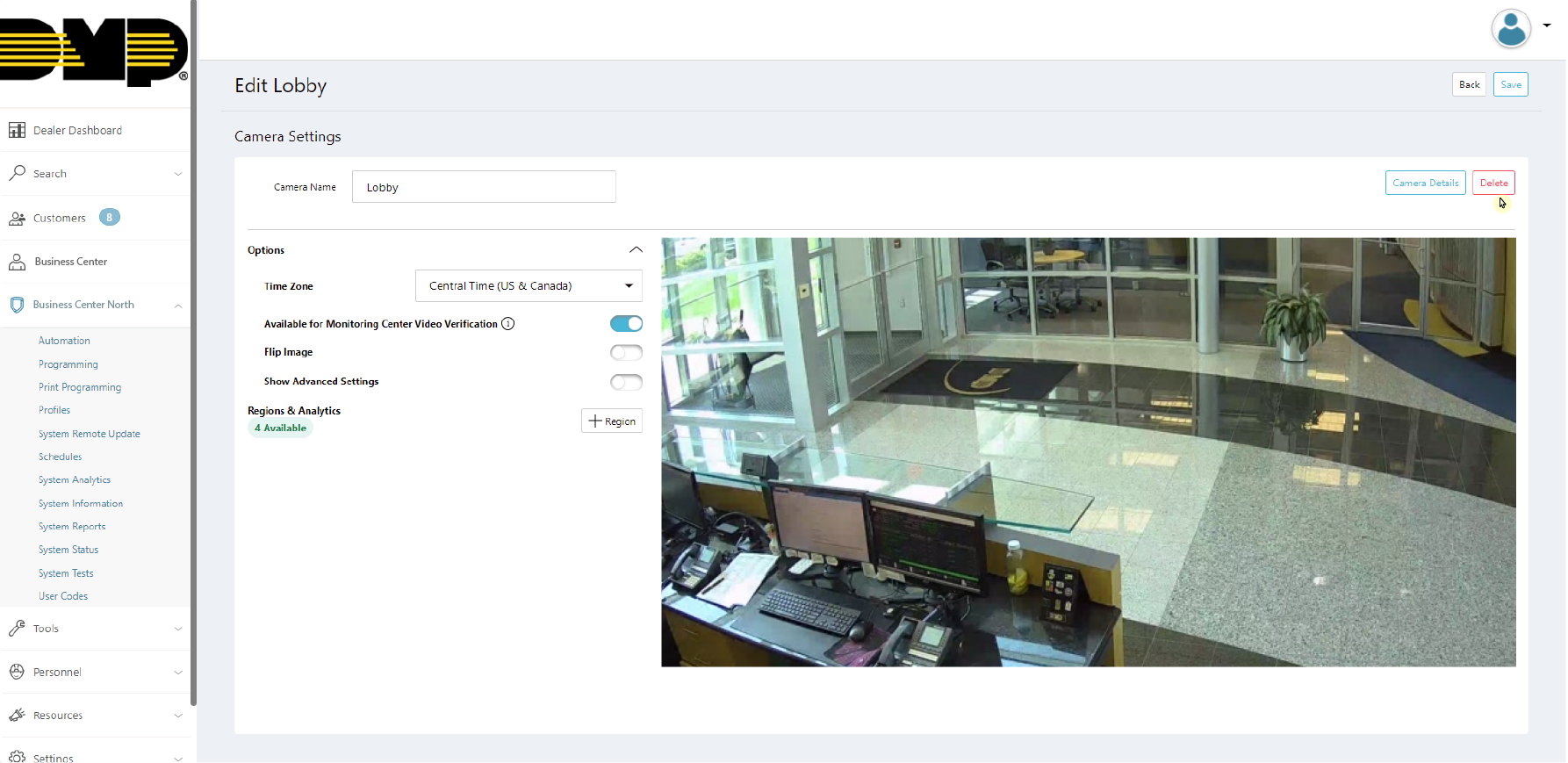
Delete a Camera
To delete a camera, navigate to System Information for the selected system.
Select the camera that you want to delete.
Select a Camera to Delete
Click Delete in the top right corner to remove the camera from the system.
Note: Deleting a camera will delete all detection regions and zones tied to the camera.
Delete Camera
Click Delete in the pop-up window to confirm that you want to delete the camera.
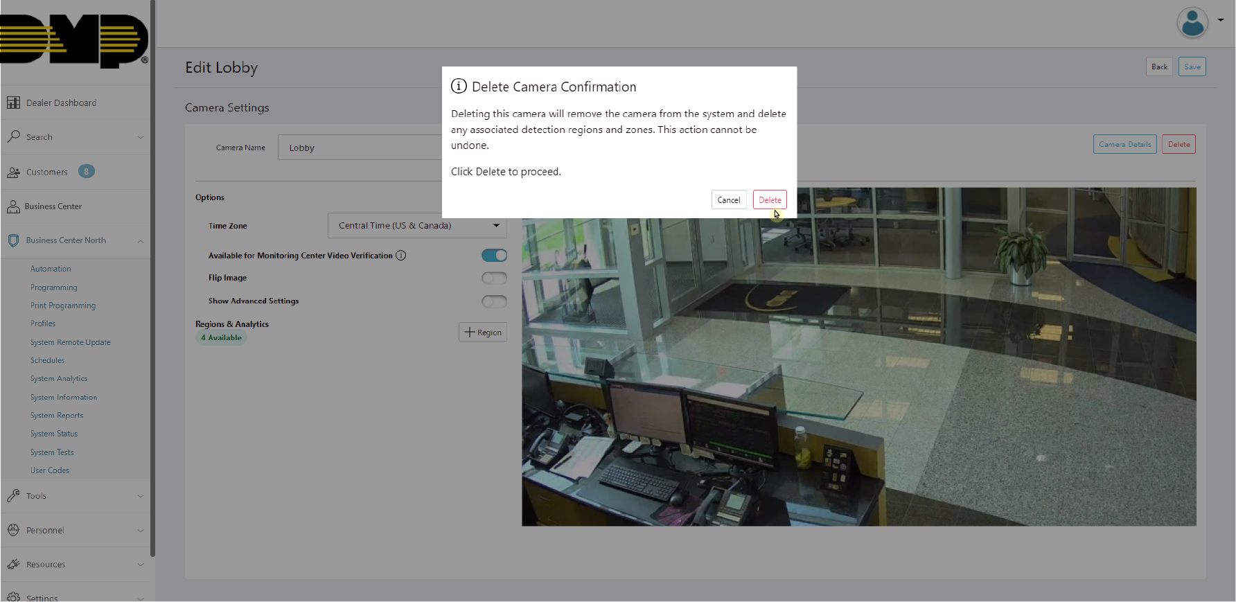
Delete Camera Confirmation
Ordering Information
Camera Models
XV-BULLET-1: 2MP Wi-Fi Bullet PoE or Wi-Fi Camera
Accessories
V-12V-PS: Camera 12V 2A Plug In Power Supply
Specifications
Camera | |
Image Sensor | 2.1 MP, 1.29” CMOS |
Resolution | 1920 x 1080 |
Minimum Illumination | Color : 0.15Lux (F1.6, 1/30sec) BW : 0Lux (IR LED on) |
Day & Night | Automatically removable infrared-cut filter |
IR Nightvision Range | Up to 98ft / 30m or more depending on the scene |
Storage | Cloud Storage |
Lens | |
Focal Length | 2.8mm Fixed Focal |
Aperture | F1.8 |
Field of View (FoV) | 105°(H) / 58.9°(V) / 122°(D) |
Video | |
Video Analytics | People / Vehicles |
Video Analytics Region Selection | Full Screen, Up to 4 Smart Zones |
Video Compression | H.264, Motion JPEG |
Resolution | Up to 1920x1080, Set by Quality Level |
Frame Rate | Video Clips: Up to 20 fps Live Video: Up to 10 fps |
Image Adjustment | Flip, Day/Night Mode, Video Quality, Frame Rate, HDR Brightness, Saturation, Contrast, Sharpness, Hue |
Video Rotation | Flip |
Network | |
Ethernet | 10/100BASE-T |
Bitrate Control | CBR / VBR |
Streaming | Unicast (3 users) |
Protocols | IPv4, TCP, UDP, RTP, RTCP, RTSP, WebRTC, NTP, HTTP, HTTPS, TLS, DHCP, ICMP, ARP, DNS |
Security | HTTP(S) login authentication, 802.1X authentication (WPA2-CCMP, WPA2-TKIP, EAP-LEAP, EAP-PEAP, EAP-TLS, EAP-TTLS, EAP-MSCHAPv2) |
Wireless | |
Wireless Connectivity | IEEE 802.11a/b/g/n |
Wi-Fi Frequency Band | 2.4GHz / 5GHz |
Wi-Fi Frequency Range | 2.412GHz ~ 2.484 GHz 5.15GHz ~ 5.85GHz |
Wireless Security | WPA, WPA2-PSK, WPA-EAP |
Environmental | |
Operating Temperature | -4°F ~ 122°F (-20°C ~ 50°C) |
Operating Humidity | Less than 90% RH |
Storage Temperature | -22°F ~ 149°F (-30°C ~ 65°C) |
Storage Humidity | Less than 90% RH |
Certification | IP66 |
Electrical | |
Input Voltage | Power over Ethernet IEEE 802.3af Class 0/12VDC ±15% |
Power Consumption | Max. 7.2W (IR On) |
General | |
Status LED | 2pcs, RGB |
Connectors | RJ45 / 5.5x2.1mm DC plug |
IR Illumination | Power-efficient, long-life 850 nm IR LEDs |
Housing Material | Aluminum |
Housing Color | RAL 9003 |
Product Dimensions | Without Antenna 3.15" x 6.42" x 3.15" (8.0 x 16.4 x 8.0cm) With Antenna 3.15" x 6.42" x 5.95" (8.0 x 16.4 x 15.1cm) |
Product Weight | Without Antenna 1.44lb / 0.65kg With Antenna 1.48lb / 0.67kg |
Included Accessories | SMA Antenna (for Wi-Fi use only), Mounting Hardware, Mounting Template |
Compliance | NDAA / TAA |
FCC Information
FCC Caution: Any changes or modifications not expressly approved by the party responsible for compliance could void the user’s authority to operate this equipment.
This device complies with Part 15 of the FCC Rules. Operation is subject to the following two conditions:
This device may not cause harmful interference, and
This device must accept any interference received, including interference that may cause undesired operation.
This device and its antenna(s) must not be co-located or operating in conjunction with any other antenna or transmitter.
The device has been evaluated to meet general RF exposure requirements. The device can be used in portable exposure conditions without restriction.
Note: This equipment has been tested and found to comply with the limits for a Class B digital device, pursuant to Part 15 of the FCC Rules. These limits are designed to provide reasonable protection against harmful interference in a residential installation. This equipment generates, uses and can radiate radio frequency energy and, if not installed and used in accordance with the instructions, may cause harmful interference to radio communications. However, there is no guarantee that interference will not occur in a particular installation. If this equipment does cause harmful interference to radio or television reception, which can be determined by turning the equipment off and on, the user is encouraged to try to correct the interference by one or more of the following measures:
Reorient or relocate the receiving antenna.
Increase the separation between the equipment and receiver.
Connect the equipment into an outlet on a circuit different from that to which the receiver is connected.
Consult the dealer or an experienced radio/TV technician for help.
FCC ID:
XV-BULLET-1: CCKXC2BPW
Industry Canada Information
IC Caution: This device complies with Industry Canada licence-exempt RSS standard(s). Operation is subject to the following two conditions:
This device may not cause interference,
This device must accept any interference, including interference that may cause undesired operation of the device.
This Class [B] digital apparatus complies with Canadian ICES-003.
Le présent appareil est conforme aux CNR d’Industrie Canada applicables aux appareils radio exempts de licence. L’exploitation est autorisée aux deux conditions suivantes:
l’appareil ne doit pas produire de brouillage, et
l’utilisateur de l’appareil doit accepter tout brouillage radioélectrique subi, même si le brouillage est susceptible d’en compromettre le fonctionnement.
Cet appareil numérique de la classe [B] est conforme à la norme NMB-003 du Canada.
L’appareil a été évalué pour répondre aux exigences générales d’exposition RF.
L’appareil peut être utilisé dans des conditions d’exposition fixes / mobiles.
Caution:
Operating Frequency Range band 5150-5250 MHz “for indoor use only.”